The restoration of a 1980's Williams Defender arcade machine
Power Supply Rebuild: Installing a new 230V Power Filter, Varistor and Fuse
So I did this part of the power supply rebuild a while ago, but never really documented “how” I did it, so thought adding this would be informative to complete the loop on what you need to do.
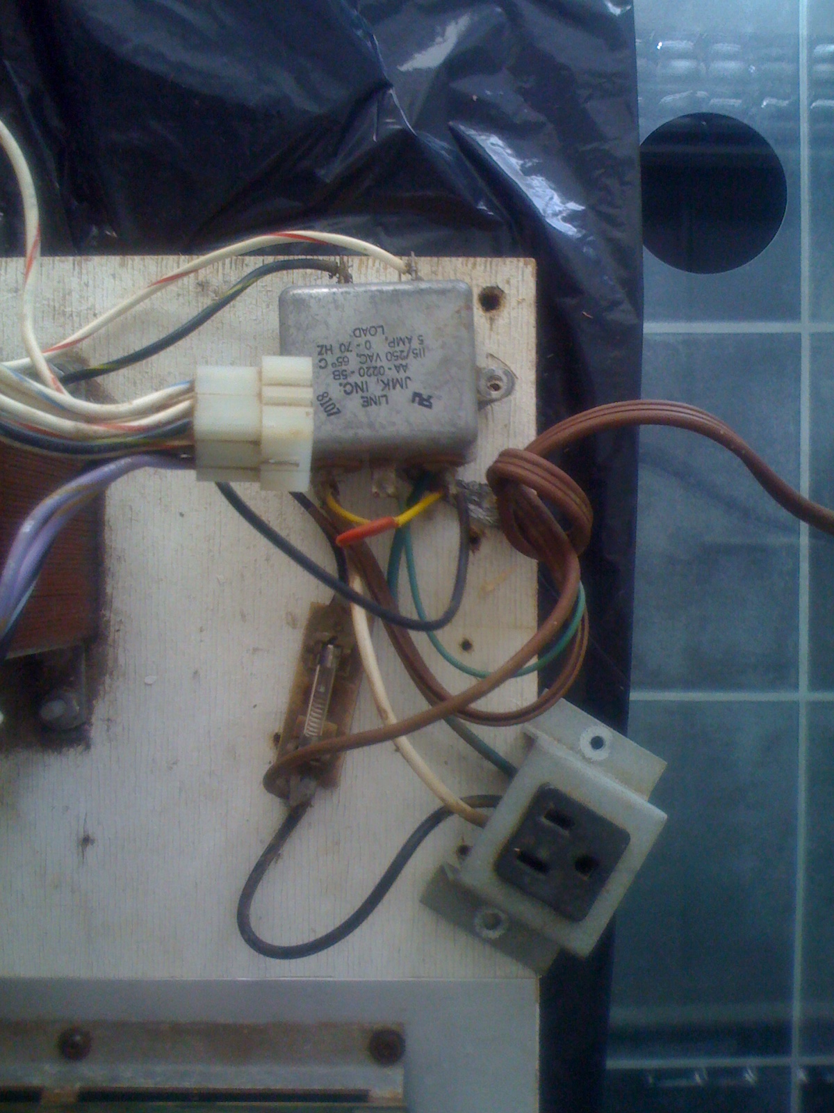
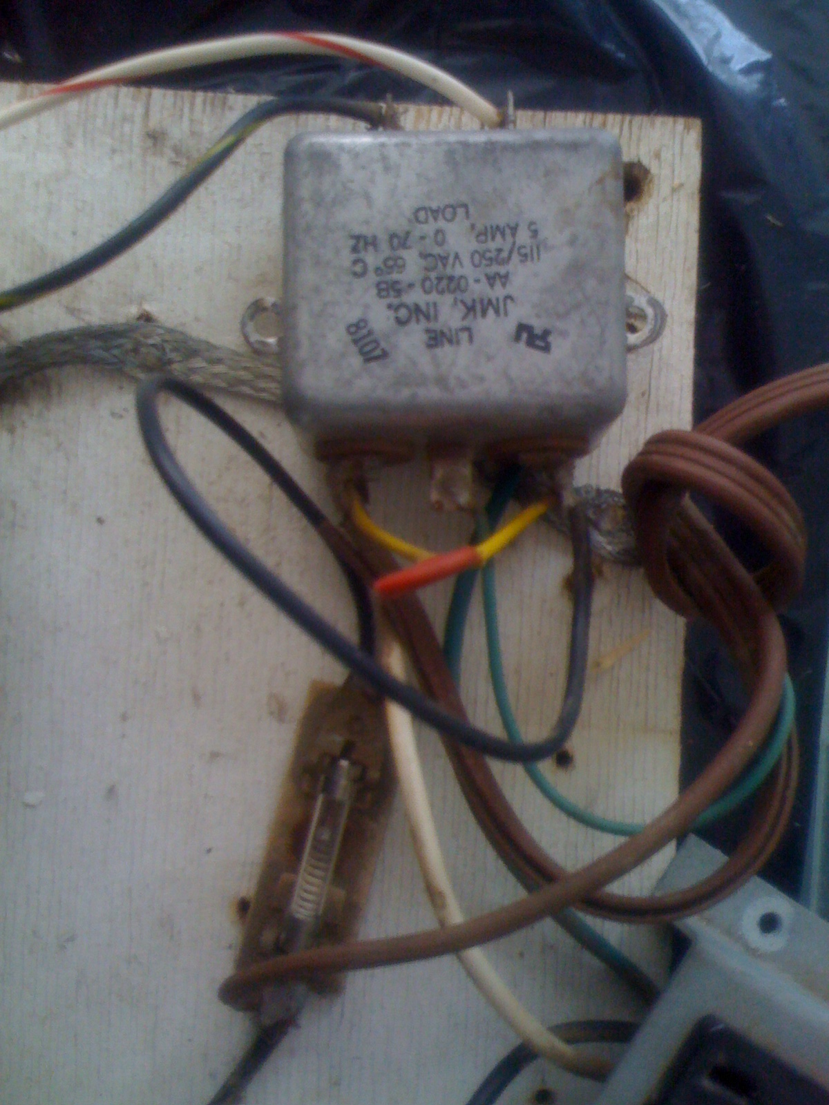
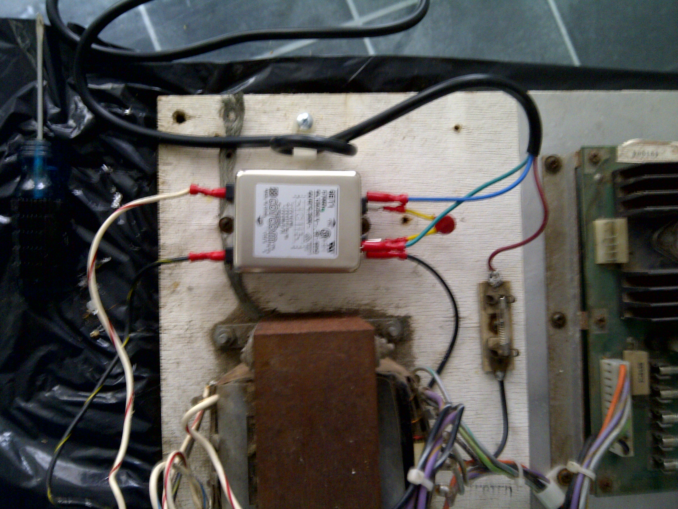
Here’s the existing power filter and varistor as it arrived from the US:
Power Filter = grey box at the top of the picture with white/red and block/yellow wires coming out of the “back” of it
Varistor = Red circular disk with yellow insulation covers around it’s legs connecting to the “front” of the power filter
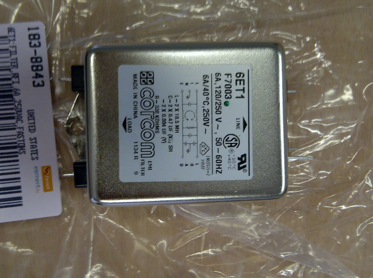
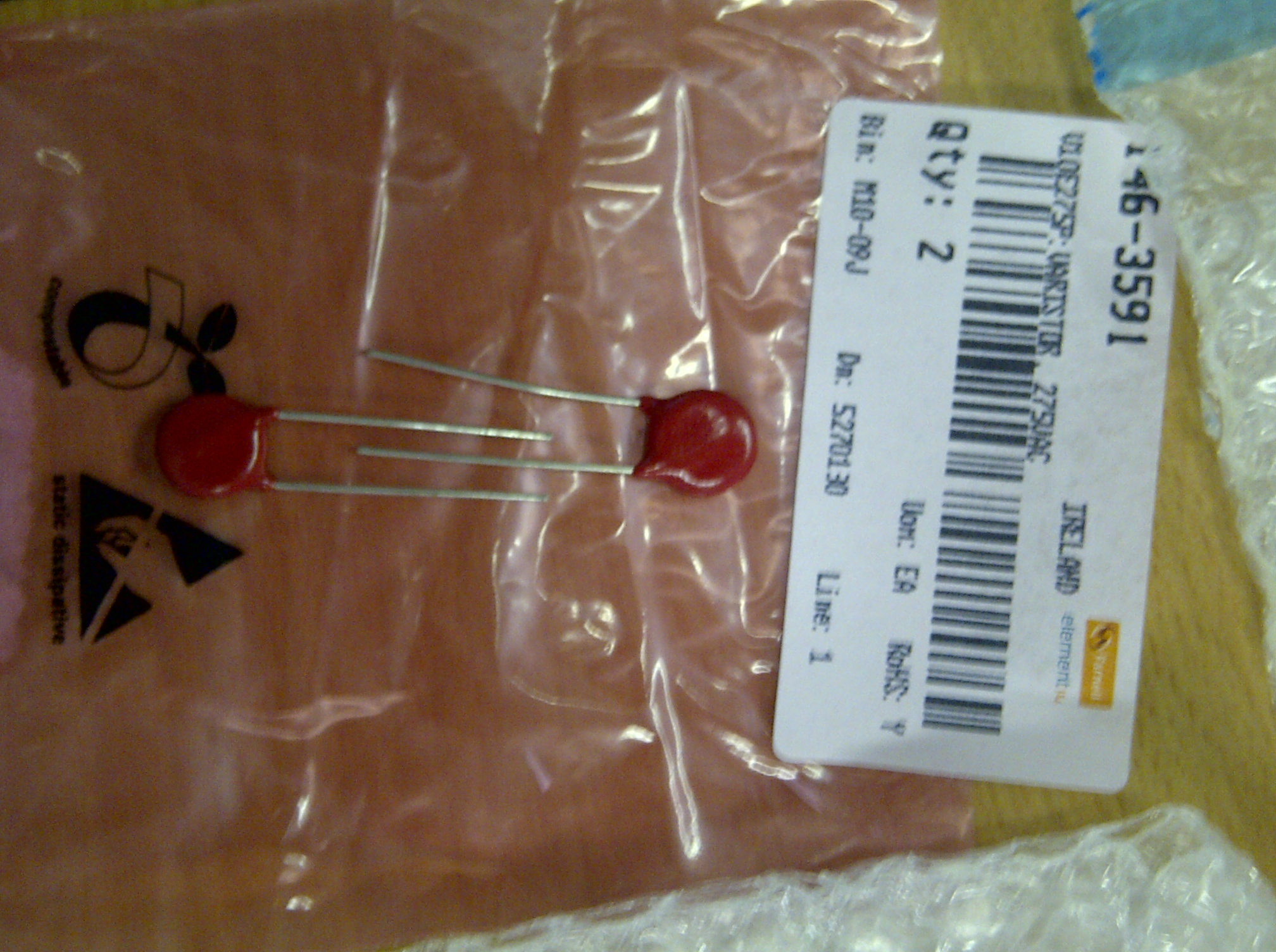
So we need a new 230/240V Power Filter, and a new 230/240V Varistor like these
Power Filter
Varistor
So in order to connect them to the existing wires, I used crimp clips on each of the wires, and ‘piggy back’ crimp sockets to connect the “front” wires and the varistor together
Basically add the yellow shielding from the original varistor to each of the new varistor legs and crimp female single ‘lucar’ crimp terminals to the end of each leg.
De-solder the existing wires from the “back” of the Power Filter and crimp female single ‘lucar’ crimp terminals to the end of each and connect to the “back” of the Power Filter.
De-solder the existing wires from the “front” of the Power Filter and crimp ‘piggy back’ crimp terminals to the end of each.
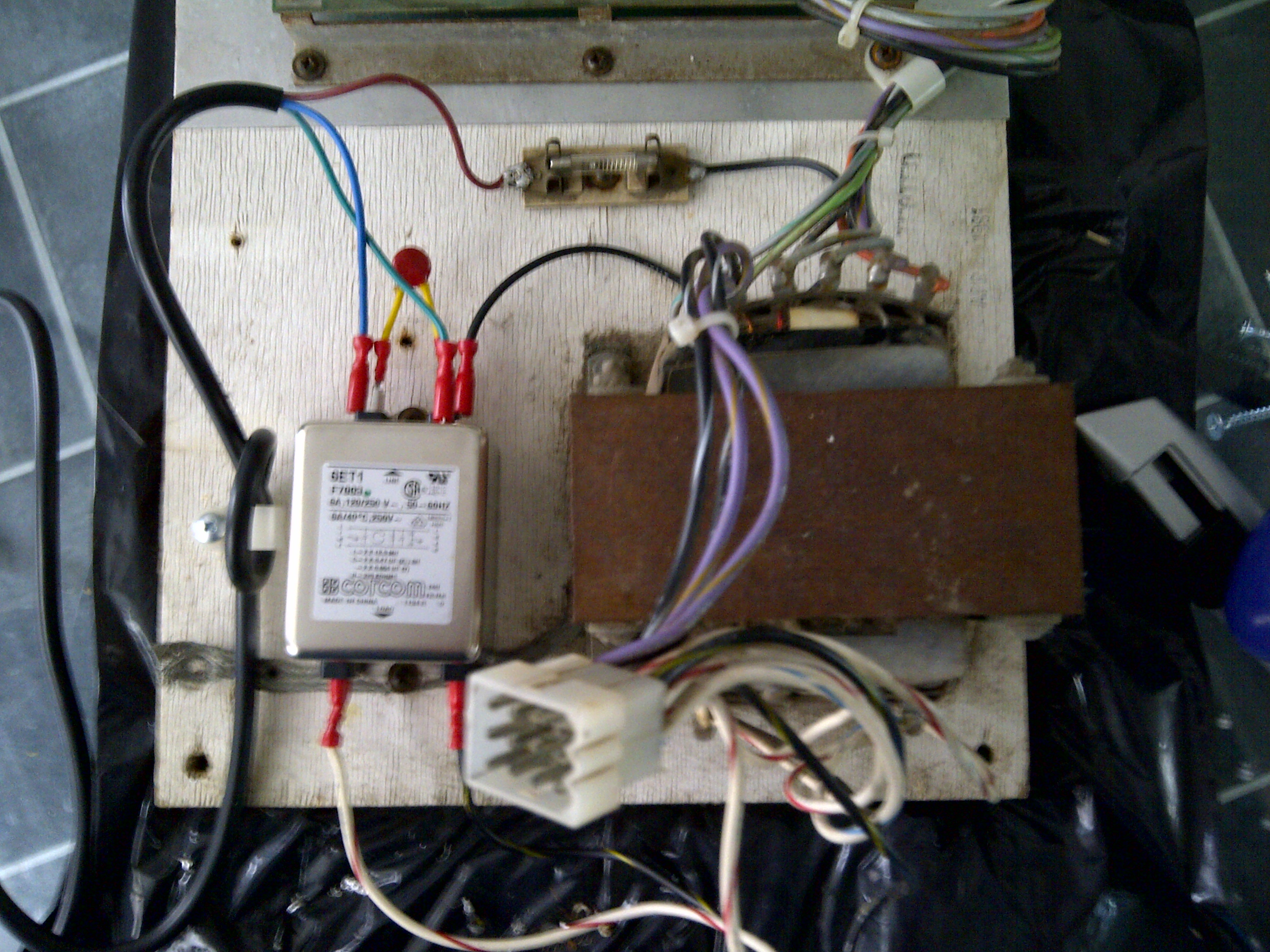
Plug the “front” wires with the piggy-back connectors into the front of the Power Filter, and plug the Varistor into the extra piggy back terminal male connector on each (see photo below)

Put the unit in place in the existing transfomer rig, make sure all of the wires are connected properly (mains AC Live and Neutral to the “front” of the Power Filter) and then you should be good to go
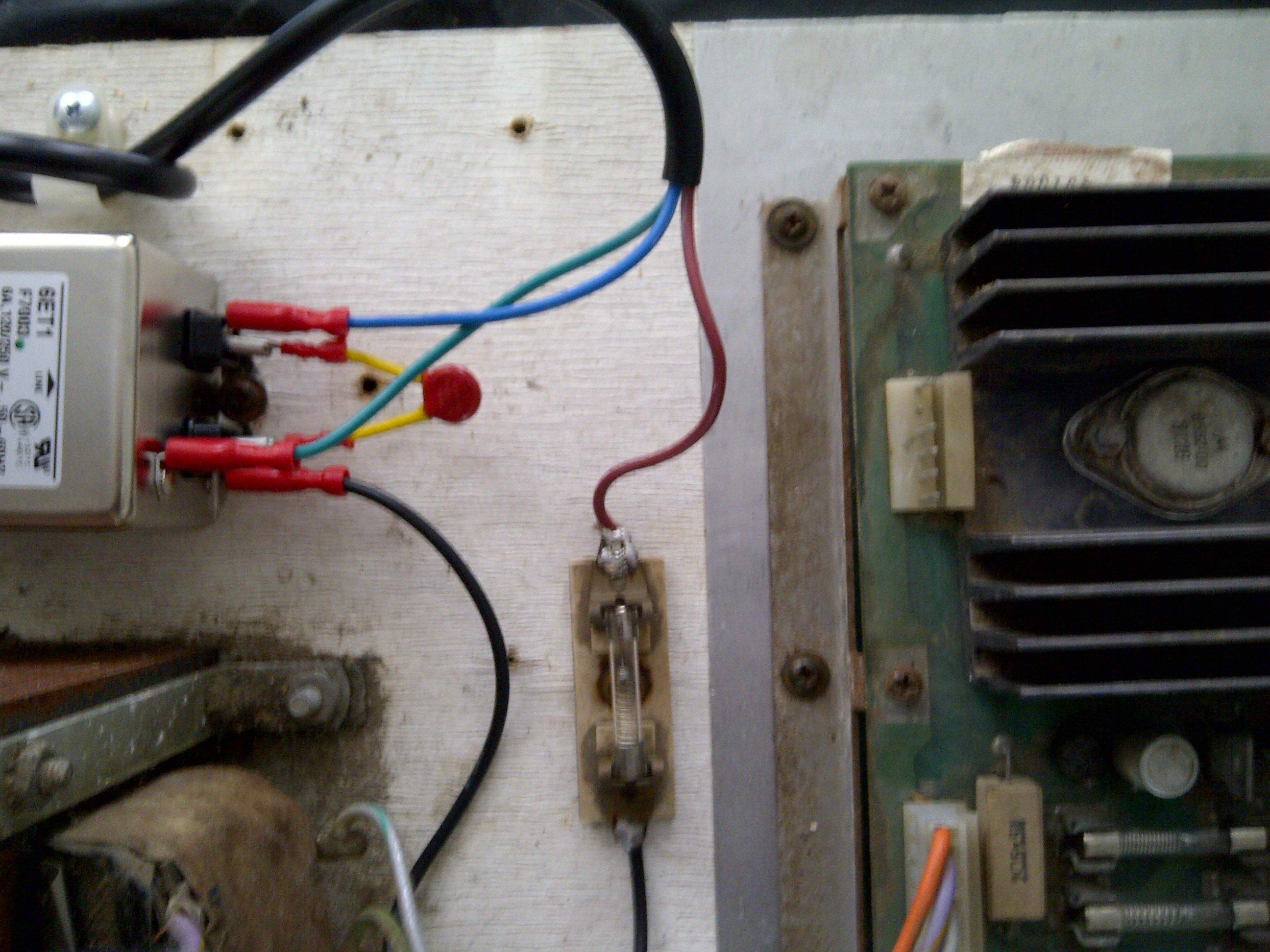
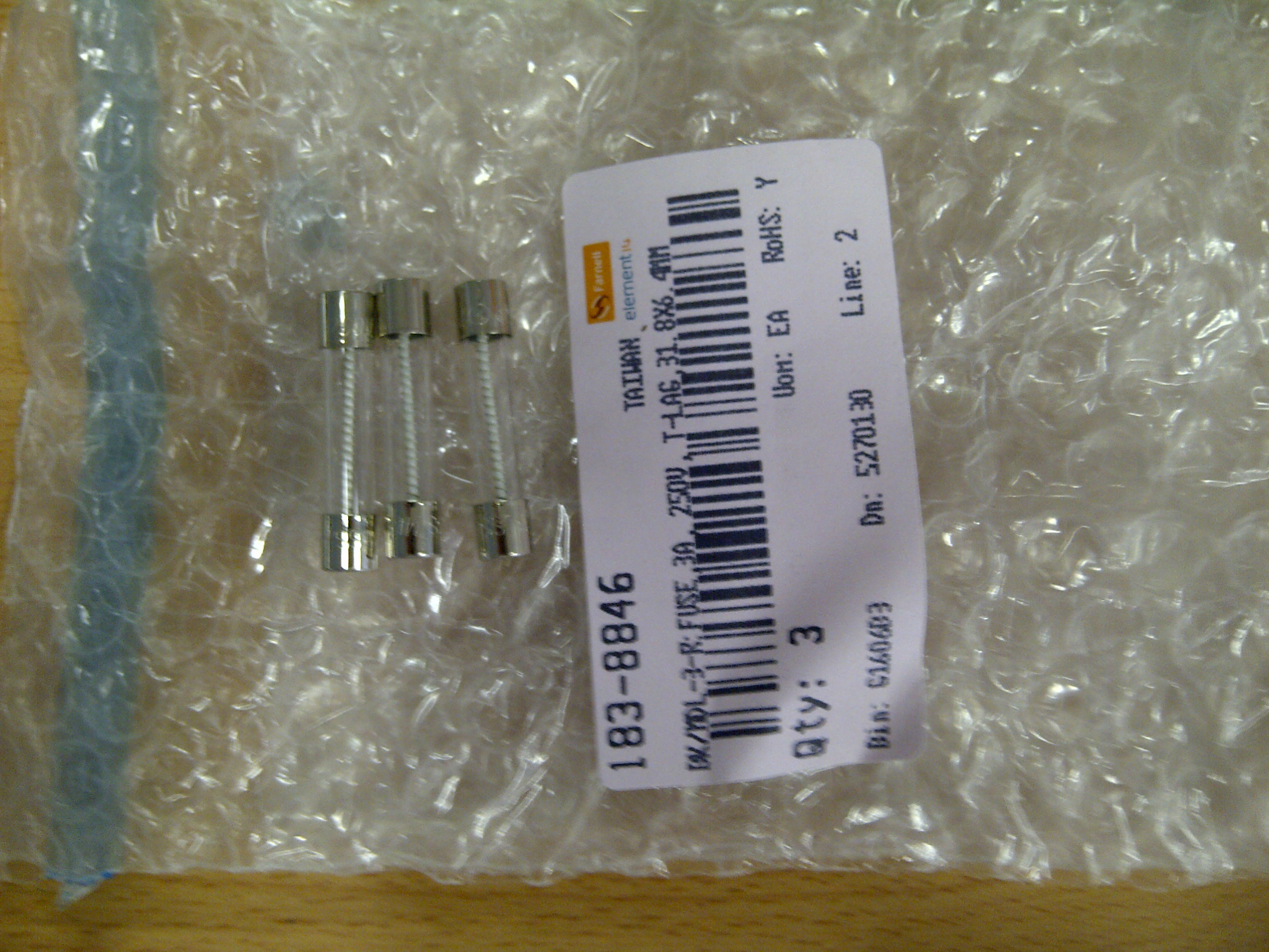
The existing 110V fuse (connected to the brown wire / Live of the wiring in the photo above) also needs to be upgraded to a 230/240V version, so I used a 3A, 250V rated glass blow fuse as follows
So the wiring is
Live (brown) -> Fuse -> Black wire -> Power Filter Live [Black covered pin]
Neutral (blue) -> Power Filter Neutral [Black covered pin]
Earth (green/yellow -> Power Filter Ground [Silver non-covered pin nearer the top of the Power Filter]
| Print article | This entry was posted by Judder on October 28, 2013 at 1:45 pm, and is filed under Power Supply Unit, Williams Defender restoration. Follow any responses to this post through RSS 2.0. Both comments and pings are currently closed. |
Comments are closed.
Recent Comments