The restoration of a 1980's Williams Defender arcade machine
Testing: Building a sound board test rig (part 1)
So.. we need sound and I need a way of testing the boards I have to see if they work, but actually switching them in and out of the main Defender cabinet is a really slow process.
Therefore – let’s build a sound board test rig and we can go through all the boards we have in one-go without needing to plug/un-plug into the main machine.
The Williams Sounds boards are actually a donation from the very popular pinball machines that Williams made, in that the ‘brains’ to do the work is all contained within one board – we just need to switch in the correct ROM image for the game we want, and test that the input connector is firing the processor (via the PIA) to make the sounds in the correct way.
First task is to give the sound board power 🙂
So you’ve been wondering what that -12V power supply is really needed for and realised that nothing much these days powers that kind of supply?
Well the good news is you can feed instead the -5V available on most arcade linear power supplies, and early ATX power supplies to do the job instead. Reference Dave’s Williams to Jamma conversion for confirmation
So were going to use +5V, -5V, +12V and ground for our power and reference the Williams’ schematics for correct wiring.
Here I’ve used a couple of old connectors that came from a Stargate machine that came in a wiring package from the US, but you can use standard crimp connectors instead.
Not the most beautiful connectors I’ve ever made but here’s the wiring:
Pin 2 – +12V DC / Unregulated
Pin 3 – +5V DC
Pin 5 – Ground
Pin 8 – -5V DV / Unregulated
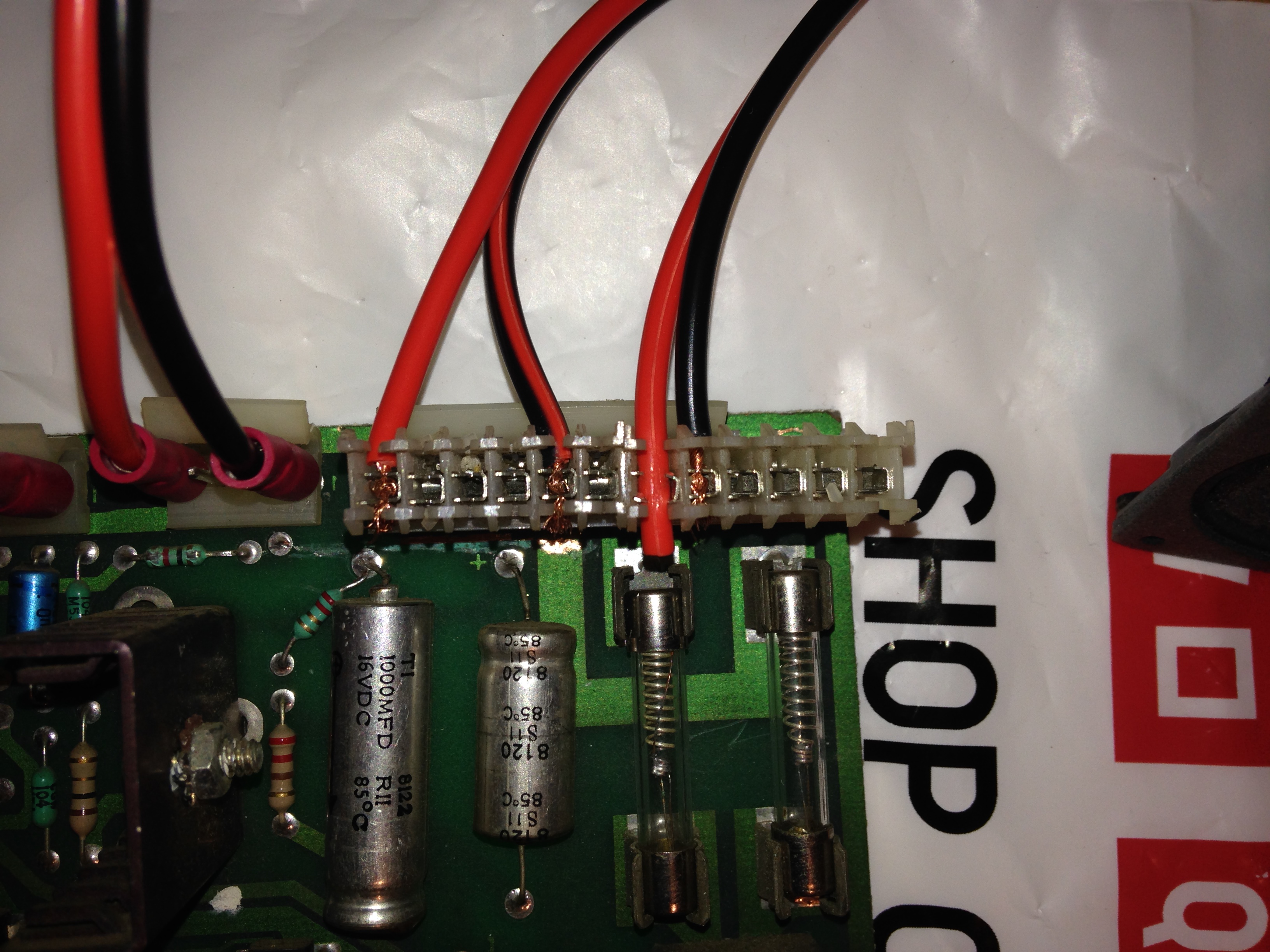
Williams Sound Board Power Wiring
Connect them up as above (note the connector in the right is too long so extra contacts aren’t used) and measure all the voltages with a multi-meter to check that we have everything coming on the correct pins where it should be.
Next we need a speaker 🙂
So mine came from an old Compaq Desktop PC we had around at the back of the office – you know the speaker that makes a beep when you turn it on? No need for that in modern day PCs – but makes a great test speaker for Williams sound boards!
To keep things clean, I left the original connectors on the speaker, and use small crimp connectors to connect directly to the speaker contacts, and large crimp connectors to connect the speaker to the board.
Pins needed are 1 and 4 (order doesn’t matter I believe) as below
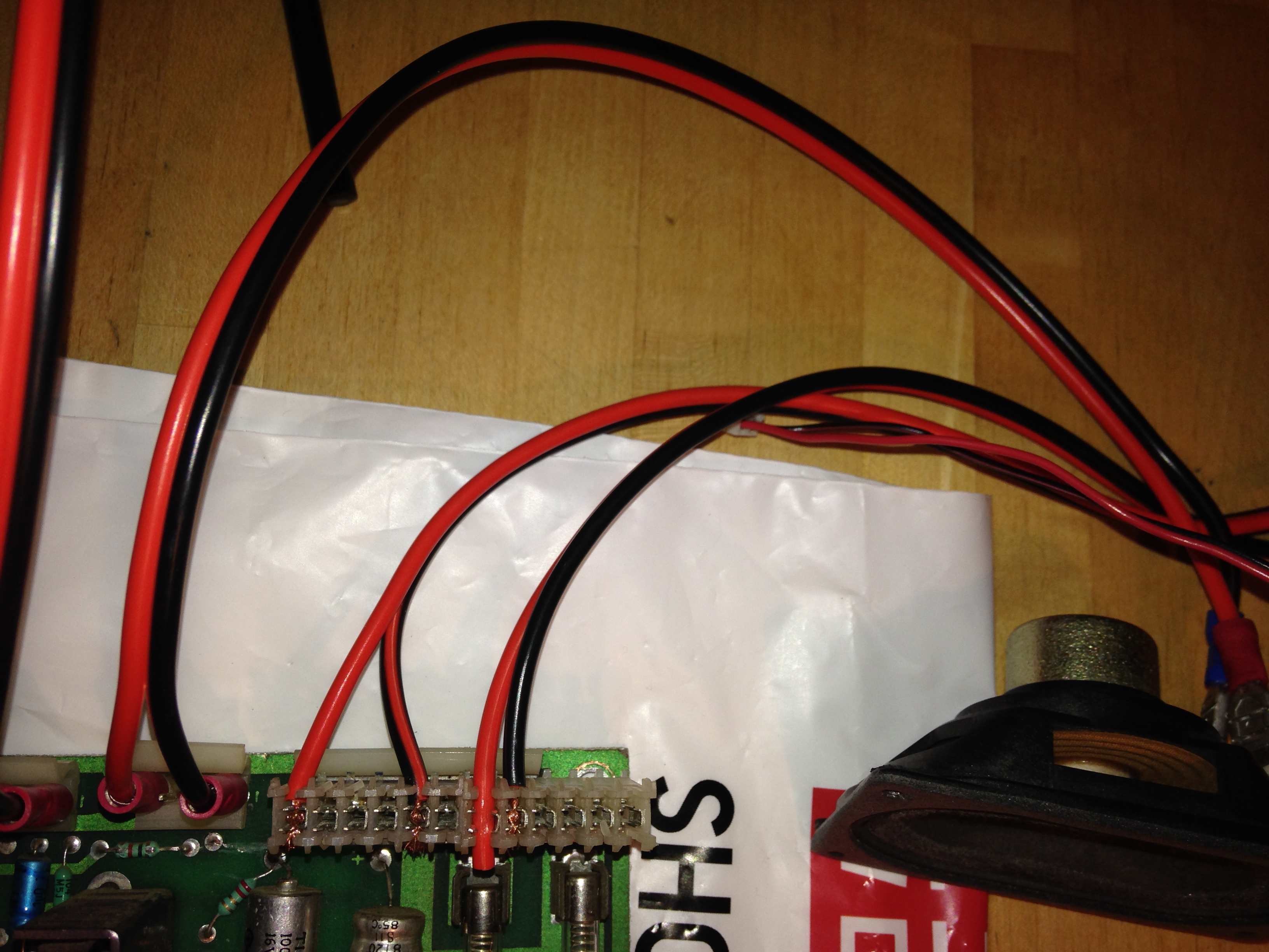
Sound Board Speaker Connected
The final part we need is a volume control to emulate the volume connector that is rigged inside the Williams cabinets.
I had a spare one kicking around, but if you don’t you can just short circuit the pins together for full volume, or raid Maplins or old electronics for one you might use – it’s only for testing so doesn’t really matter.
Pins need are 1 and 2 as per this picture – again I don’t believe order matters
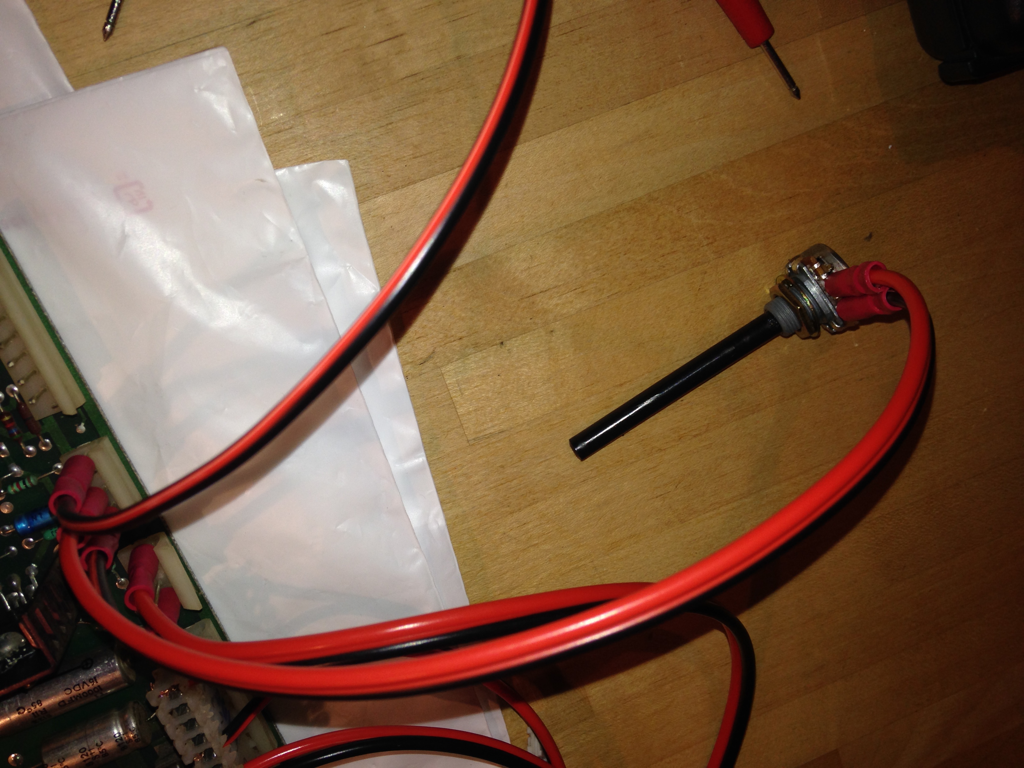
Volume Control Connected
Final job is to power it all up and test it out!
First thing to do is test the power voltages using a multi-meter across the main 3 capacitors shown in the top right of this picture.
Top of the board is ground, and I can’t remember the order but they should register +5V, -5V and +12V each (to do: add link to pinball site explaining which does which)
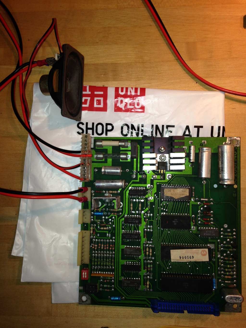
Capacitors to test voltages
Last step is to rig up some way of testing the sounds (you can of course just press the test button to get sounds, but Defender seems to only play a single sound when you do this, not loop through all the sounds)
To do this we will use Pin 4 of the speaker connection (common / ground) and a bare end to test the contacts on the input to the PIA controller.
As they say a video speaks a thousand words, so here’s me doing exactly that 🙂
— to be continued in part 2
| Print article | This entry was posted by Judder on December 11, 2013 at 8:48 pm, and is filed under The Boards, Williams Defender restoration. Follow any responses to this post through RSS 2.0. Both comments and pings are currently closed. |
Comments are closed.
Recent Comments